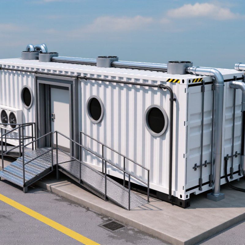
| MRI System |
Static magnetic field strength |
Confirm the scanner rating, such as 1.5 T or 3 T, before finalizing the shielding, access-control, and fringe-field design. |
Review the approved equipment specification and the manufacturer’s magnetic-field contour drawings. |
Design stage |
Required |
| Magnetic Safety |
Fringe-field boundary |
Define the controlled-access boundary using the actual 5-gauss contour and other project-specific safety limits. The boundary is not determined by room size alone. |
Confirm the calculated contour with a qualified MRI physicist and verify it by calibrated gauss-meter survey after installation. |
Design and commissioning |
Required |
| RF Shielding |
Shield enclosure continuity |
Use a continuous conductive enclosure on the walls, ceiling, and floor, with electrically bonded joints and compatible materials selected for the MRI operating frequency. |
Inspect seams, overlaps, fasteners, floor transitions, and wall-to-ceiling interfaces before concealment. |
Installation |
Hold point |
| RF Shielding |
RF attenuation performance |
Set project-specific attenuation targets in the design specification. Acceptance limits depend on field strength, operating frequency, site noise, and the imaging system. |
Perform calibrated RF leakage and attenuation testing at representative frequencies after all penetrations and doors are complete. |
Commissioning |
Test required |
| Doors and Seams |
RF door contact integrity |
Ensure continuous, clean, unobstructed contact fingers or gaskets around the complete door perimeter. The door must close evenly without excessive force. |
Visually inspect the contact system, check alignment and compression, and repeat RF testing with the door closed. |
Installation and handover |
Inspect |
| Penetrations |
Services crossing the shield |
Route power, data, fire alarm, lighting, plumbing, and monitoring services through engineered RF filters, waveguides, or bonded penetration assemblies. |
Verify that each penetration has an approved detail, correct bonding, strain relief, and no unsealed gap around the service. |
Before concealment |
Hold point |
| Electrical Safety |
Equipotential bonding and grounding |
Bond the RF enclosure and conductive building elements according to the electrical design and the locally adopted medical-location requirements. Avoid unintended parallel current paths. |
Inspect bonding conductors and connection points; measure continuity and document the results using calibrated instruments. |
Installation and testing |
Required |
| Ventilation |
Normal air-change design |
Size supply and exhaust airflow from the calculated heat load, occupancy, equipment requirements, and locally adopted mechanical-code criteria. Do not use a generic air-change rate without a load calculation. |
Review mechanical calculations and balance the installed system; record supply and extract airflow at the room terminals. |
Design and commissioning |
Required |
| Ventilation |
Quench exhaust route |
Where a superconducting magnet and cryogen system are used, provide a dedicated quench exhaust path designed for rapid discharge of helium and pressure relief to a safe outdoor location. |
Inspect pipe routing, supports, joints, discharge location, weather protection, and separation from air intakes and occupied areas. |
Installation |
Hold point |
| Ventilation |
Oxygen-deficiency protection |
Assess the credible helium-release scenario. Provide oxygen monitoring, audible and visual alarms, and emergency ventilation where required by the risk assessment and local code. |
Test sensor calibration, alarm set points, emergency exhaust operation, backup power, and the cause-and-effect sequence. |
Commissioning |
Test required |
| Container Structure |
Movement and differential deflection |
Design the RF enclosure and service connections for transport loads, lifting, foundation movement, thermal expansion, and vibration without opening shield joints. |
Review structural calculations and inspect the enclosure after delivery, positioning, leveling, and final connection of services. |
Delivery and installation |
Required |
| Fire and Life Safety |
Fire stopping and egress |
Maintain fire-rated penetrations, accessible escape routes, emergency lighting, door hardware, and alarm coverage in accordance with the locally adopted building and fire codes. |
Obtain inspection records, fire-stopping certificates, emergency-lighting test results, and authority approvals where applicable. |
Handover |
Required |
| Environmental Control |
Temperature and humidity |
Keep the MRI room and equipment spaces within the imaging-system environmental limits stated in the approved equipment specification; stable conditions are essential for reliable operation. |
Trend temperature and relative humidity under normal operating conditions and verify alarms at the control system. |
Commissioning |
Record |
| Site Quality |
Pre-concealment inspection |
Do not close walls, ceilings, floors, or service chases until shielding seams, penetrations, bonds, filters, and door frames have been inspected and photographed. |
Use a signed inspection checklist with marked-up drawings, photographs, material records, and corrective-action closeout. |
Construction |
Hold point |
| Compliance |
Applicable standards and approvals |
Coordinate the project with the latest locally adopted requirements, including MRI equipment safety, electrical safety, medical-location rules, building regulations, fire codes, and radiation-protection requirements where applicable. |
Maintain a compliance matrix identifying each requirement, responsible party, evidence, inspection date, and approval authority. |
All phases |
Required |
| Final Acceptance |
Integrated performance test |
Accept the containerized suite only after RF shielding, magnetic-field zoning, ventilation, oxygen-deficiency protection, electrical safety, fire safety, and operational controls have passed. |
Issue a commissioning report containing test instruments, calibration dates, measured results, drawings, photographs, deviations, and sign-offs. |
Handover |
Acceptance gate |
 Aert Medical